Explore - Design - Develop
Explore - Design - Develop
version 1.2.0
1.1 Functionality and Features
Appendix 1: Klapp Internal Database
Klapp is a plugin for Revit that simulates the propagation of sound waves inside a selected Room in a Revit project. It allows the user to compute and analyze the acoustical properties of any Room as early as the design phase of the project.
The plugin is a powerful tool that uses the principles of geometrical acoustics to conduct the sound wave propagation simulation. In its core functionality, it can be compared with specialized room acoustics simulation software, such as Odeon and Sarooma.
Klapp is developed as part of Project BG 16RFOP002-2.024-0089 “Promotion of entrepreneurship in MAULBEER Ltd", financed by the Operational Programme “Innovation and competitiveness” 2014-2020, co-financed by the European Union through the European Regional Development Fund.
Klapp simulates the propagation of sound waves between an omni-directional Sound Source and a specified Observation Point inside the selected Room. The Room, Sound Source and Observation Point can be freely selected by the user. After the simulation is completed Klapp presents the acoustical characteristics of the selected Room at the Observation Point.
Klapp calculates the properties of the sound at a particular point (observation point), given a defined static sound source that is not the same point as the observation point. Both points must be inside the selected virtual sound space (room).
In other words, Klapp computes how the sound produced by the sound source is altered by the sound space when “listening” at the specified observation point. A practical example where all this can be applied is in designing conference rooms. Klapp can compute how well a listener in the audience (observation point) can hear the speaker at the podium (sound source) when attending a talk in the conference room (sound space).
The main features of Klapp are:
Allows Autodesk Revit users to analyze the acoustic properties of the designed rooms.
Applies the principles of geometrical acoustics to produce perceptually plausible room acoustics simulation results.
Clean and intuitive user interface, giving users the ability to use the plugin without needing extensive knowledge in the field of acoustics.
Klapp is a complex plugin that aims to extend Revit’s functionality in a new direction. Although we are continuously improving it, it still has several limitations to its functionality. Please, check Section 2 (Before Using Klapp) and Section 4 (Known Limitations) for more information.
Furthermore, due to the limitations of geometrical acoustics, Klapp only achieves “perceptually plausible” results. This means that the simulation produces results that may not precisely represent real sound propagation, but are very close, i.e. the results sound plausible to the naked ear, but may not perfectly represent reality.
Klapp extends Revit’s functionality in a new direction. Even though the design philosophy behind Klapp is to be as intuitive and convenient for the user as possible, it still cannot fully automate its behavior through the Revit API. Therefore, the user is required to set up their Revit project as specified below, before using Klapp.
The instructions in this section apply after Klapp is successfully installed. If done correctly, the user only needs to do this once per project.
Klapp can perform acoustical analysis only on spaces that are defined as a Room in the Revit project.
Furthermore, each Room must have its Upper Limit and Offset set in the following way:
Upper Limit: The upper limit of the Room must be the same level as the ceiling of the space that the Room encompasses, or higher. For example, if a Room’s level is Floor 1, its upper limit should be set to Floor 2.
Offset: If applied, the offset must be set such that the height of the Room covers the ceiling of the space that the Room encompasses. For example, it is alright if the Room is higher than the ceiling, by setting its offset positive. However, it cannot be lower than the ceiling, e.g. when the applied offset is large and negative.
If the Room is not set as described above, Klapp would not be able to correctly determine the dimensions, shape and construction materials of the Room.
In order to simulate sound propagation through a virtual space, Klapp needs information about the sound absorption qualities of the material(s) of each surface. Unfortunately, by default, materials in Revit do not contain any sound absorption information.
To overcome this issue, Klapp implements an internal database that contains the sound absorption characteristics of various common construction materials. The user is required to manually update the materials that appear on the internal surfaces of the Room (walls, floor and ceiling) to link them to the Klapp internal database, by using the Material Browser.
The Klapp internal database is presented in Appendix 1. It lists all construction materials that Klapp supports, along with their corresponding database entry names. All entry names in the Klapp database begin with the characters “Aco_”.
To link a material inside the Revit project to the Klapp internal database
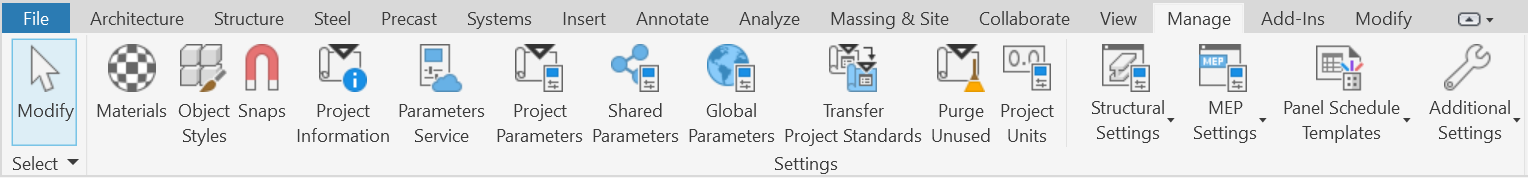
Open the Material Browser by selecting Manage -> Materials.
Select a material that composes an internal surface of the Room.
Add the entry name from the Klapp material database that corresponds to the selected material. The entry must be specified in either the material’s Name or Class fields.
The entry name must be separated from any other text in the field by at least one empty space. If the entry name is specified in both fields, Klapp will select the one from the Name field.
For example, the material Brick in the screenshot below includes the label Aco_Brick_Painted in both its Name or Class fields.
Important: If the selected Room does not have all of its internal surfaces composed of properly updated materials, Klapp will not be able to perform the acoustic simulation.
To start Klapp, first navigate to the Add-Ins ribbon panel inside Revit. Then click on the Acoustic Analyser button inside the Klapp section of the Add-Ins panel.
When Klapp starts it displays the following GUI form:
Before analyzing the properties of the acoustic space with Klapp, the user must select three components: the Room, the Sound Source coordinates and the Observation Point coordinates. See the following three subsections for more information.
Important: Select the input for Klapp only through a Floor Plan View in the Revit project. Klapp does not yet support selecting input through a Section View or a 3D View.
Select the room which is to be analyzed using the selection tool. This must be an enclosed area, specified as a “Room” in the Revit project.
Select the location of the sound source on the XY plane using the selection tool. The selected sound source must be inside the selected room. After selecting the location on the XY plane of the Room, Klapp will display a pop-up asking for the Z-Coordinate of the sound source.
Select the location of an observation point on the XY plane using the selection tool. The selected observation point must be inside the selected room. After selecting the location on the XY plane of the Room, Klapp will display a pop-up asking for the Z-Coordinate of the observation point.
The only configuration parameter, apart from the Room, Sound Source and Observation Point, is Reflections Order. It allows the user to specify the maximum number of consecutive reflections per sound wave that will be computed. The larger the maximum number of computed consecutive reflections, the more accurate the simulation. However, setting the Reflections Order very high would result in slower performance due to the complexity of calculating sound waves. Therefore, Reflections Order is a configuration parameter that provides a tradeoff between accuracy and performance.
The Reflections Order default value of 10 is considered accurate to the point of perceptual plausibility and does not hinder performance. Reflections Order lower than 5 is not sufficient for accurate simulation.
To run the Klapp simulation with the given input parameters, press the Run Acoustic Analysis button.
The simulation results consist of two main components:
The Impulse Response describes the “reaction” of the simulated space to an emitted sound as 16a function of time. It shows how much the sound is delayed and attenuated after traveling through the space, from the sound source to the observation point, and being reflected from the surfaces that define the space. The longer the impulse response, the longer the echo that the space produces. Long echos can have a pleasing sound to the ear, but may make the speech more difficult to understand.
In the simulation performed by Klapp, the sound source creates a digital impulse to be used for the analysis of the space. After running the digital impulse through the sound wave propagation algorithm, the resulting impulse response contains all the necessary information about the acoustical properties of the selected Room at the selected Observation Point.
The Impulse Response plot shows the temporal information of the acoustic properties of the space. It displays the delay and attenuation of the sound due to the geometry of the space. The X axis of the plot represents time in seconds. The Y axis represents the amplitude of the impulse response, in values between 1 and -1.
The Frequency Response is a representation of the impulse response in the frequency domain.In other words, it represents the frequency coloration of the sound traveling from the sound source to the observation point, based on the virtual space geometry. Klapp achieves this by performing Fast Fourier Transform on the calculated impulse response.
The Frequency Response plot shows the frequency information of the acoustic properties of the space. It displays how the space geometry alters the properties of the sound, i.e. which frequencies are increased or reduced and by how much. The X axis of the plot represents the frequencies between 20 Hz and 20 kHz, which is the hearing range of humans. The Y axis represents the Gain (or attenuation) of each frequency in dB.
To save the entire simulation information, including input data and the produced results, into a .txt file, the “Save Results” button at the bottom. This can be used for further statistical analysis or for information completeness in an architectural project.
Although functional, this current version of Klapp still possesses a few major limitations. These are listed below:
Klapp utilizes geometrical acoustics for its simulation. Therefore, it is not as accurate as specialized simulations that use differential equations. It achieves “perceptually plausible” results, which means that it provides the user with fairly accurate, but not necessarily exact, information about the acoustic properties of the selected Room. This means that, once actually built, the space represented by the selected Room may not sound exactly like the simulation results.
Klapp cannot handle curved surfaces. Klapp can only handle Rooms that consist only of flat surfaces.
Klapp cannot yet properly simulate large windows or curtain walls. Therefore, the user should avoid using Klapp in Rooms with large windows. Klapp will be able to perform the simulation, but the results may be less accurate.
Klapp does not explicitly simulate furniture in the Room. While its core algorithm does apply filtering that somewhat approximates the effect of furniture on the propagation of sound waves, the simulation may become less accurate if there is a lot of furniture in the Room.
Klapp offers minor accessibility options. The user can change the UI font size, by using the dedicated buttons:
Table 1 contains all materials that are supported by Klapp. The table lists the actual name of the material and its corresponding entry in the Klapp Internal Database. The user does not need to know about the actual sound absorption characteristics of each material. They just need to specify what the material is in their Revit project.
The absorption coefficients of each material are taken from the JSWA Acoustic Supplies’ “Absorption coefficients of common building materials and finishes” table, see https://www.acoustic-supplies.com/absorption-coefficient-chart/.
Table 1: Supported materials
|
Material Name
|
Klapp Internal Database Entry
|
|
Floor Materials |
|
|
Carpet |
Aco_Carpet |
|
Concrete (unpainted, rough finish) |
Aco_Concrete_UnpaintedRoughFinish |
|
Concrete (sealed or painted) |
Aco_Concrete_SealedOrPainted |
|
Marble or glazed tile |
Aco_Tile_MarbleOrGlazed |
|
Vinyl tile or linoleum on concrete |
Aco_Tile_VinylOnConcrete |
|
Wood parquet on concrete |
Aco_Wood_Parquet_On_Concrete |
|
Wood flooring on joists |
Aco_Wood_Flooring_On_Joists |
|
Reflective Wall Materials |
|
|
Brick (natural) |
Aco_Brick_Natural |
|
Brick (painted) |
Aco_Brick_Painted |
|
Concrete block (coarse) |
Aco_ConcreteBlock_Coarse |
|
Concrete block (painted) |
Aco_ConcreteBlock_Painted |
|
Concrete (poured, rough finish, unpainted) |
Aco_Concrete_PouredRoughUnpainted |
|
Doors (solid wood panels) |
Aco_Doors_SolidWoodPanels |
|
Glass (1/4″ plate, large pane) |
Aco_Glass_LargePane |
|
Glass (small pane) |
Aco_Glass_SmallPane |
|
Plasterboard (12mm (1/2″) paneling on studs) |
Aco_Plasterboard_PanelingOnStuds |
|
Plaster (gypsum or lime, on masonry) |
Aco_Plaster_GypsumOrLime_OnMasonry |
|
Plaster (gypsum or lime, on wood lath) |
Aco_Plaster_GypsumOrLime_OnWoodLath |
|
Plywood (3mm(1/8″) paneling over 31.7mm(1-1/4″) airspace) |
Aco_Plywood_3mmPaneling_Over_31p7mmAirspace |
|
Plywood (3mm(1/8″) paneling over 57.1mm( 2-1/4″) airspace) |
Aco_Plywood_3mmPaneling_Over_57p1mmAirspace |
|
Plywood (5mm(3/16″) paneling over 50mm(2″) airspace) |
Aco_Plywood_5mmPaneling_Over_50mmAirspace |
|
Plywood (5mm(3/16″) panel, 25mm(1″) fiberglass in 50mm(2″) airspace) |
Aco_Plywood_5mmPanel_25mmFiberglass_In_50mmAirspace |
|
Plywood (6mm(1/4″) paneling, airspace, light bracing) |
Aco_Plywood_6mmPaneling_Airspace_LightBracing |
|
Plywood (10mm(3/8″) paneling, airspace, light bracing) |
Aco_Plywood_10mmPaneling_Airspace_LightBracing |
|
Plywood (19mm(3/4″) paneling, airspace, light bracing) |
Aco_Plywood_19mmPaneling_Airspace_LightBracing |
|
Absorptive Wall Materials |
|
|
Drapery (10 oz/yd2, 340 g/m2, flat against wall) |
Aco_Drapery_340g_m2_FlatAgainstWall |
|
Drapery (14 oz/yd2, 476 g/m2, flat against wall) |
Aco_Drapery_476g_m2_FlatAgainstWall |
|
Drapery (18 oz/yd2, 612 g/m2, flat against wall) |
Aco_Drapery_612g_m2_FlatAgainstWall |
|
Drapery (14 oz/yd2, 476 g/m2, pleated 50%) |
Ao_Drapery_476g_m2_Pleated50Percent |
|
Drapery (18 oz/yd2, 612 g/m2, pleated 50%) |
Aco_Drapery_612g_m2_Pleated50Percent |
|
Fiberglass board (25mm(1″) thick) |
Aco_FiberglassBoard_25mmThick |
|
Fiberglass board (50mm(2″) thick) |
Aco_FiberglassBoard_50mmThick |
|
Fiberglass board (75mm(3″) thick) |
Aco_FiberglassBoard_75mmThick |
|
Fiberglass board (100mm(4″) thick) |
Aco_FiberglassBoard_100mmThick |
|
Open brick pattern over 75mm(3″) fiberglass |
Aco_OpenBrickPattern_Over_75mmFiberglass |
|
Pageboard over 25mm(1″) fiberglass board |
Aco_Pageboard_25mmFiberglassBoard |
|
Pageboard over 50mm(2″) fiberglass board |
Aco_Pageboard_50mmFiberglassBoard |
|
Pageboard over 75mm(3″) fiberglass board |
Aco_Pageboard_75mmFiberglassBoard |
|
Performated metal (13% open, over 50mm(2″) fiberglass) |
Aco_PerformatedMetal_13PercentOpen_Over_50mmFiberglass |
|
Ceiling Materials |
|
|
Plasterboard (12mm(1/2″) in suspended ceiling grid) |
Aco_Plasterboard_12mm_In_SuspendedCeilingGrid |
|
Underlay in perforated metal panels (25mm(1″) batts) |
Aco_Underlay_In_PerforatedMetalPanels_25mmBats |
|
Metal deck (perforated channels,25mm(1″) batts) |
Aco_MetalDeck_PerforatedChannels_25mmBats |
|
Metal deck (perforated channels, 75mm(3″) batts) |
Aco_MetalDeck_PerforatedChannels_75mmBats |
|
Plaster (gypsum or lime, on masonry) |
Aco_Plaster_GypsumOrLime_OnMasonry |
|
Plaster (gypsum or lime, rough finish or timber lath) |
Aco_Plaster_GypsumOrLime_RoughFinishOrTimberLath |
|
Sprayed cellulose fiber (16mm(5/8″) on solid backing) |
Aco_SprayedCelluloseFiber_16mm_On_SolidBacking |
|
Sprayed cellulose fiber (25mm(1″) on solid backing) |
Aco_SprayedCelluloseFiber_25mm_On_SolidBacking |
|
Sprayed cellulose fiber (25mm(1″) on timber lath) |
Aco_SprayedCelluloseFiber_25mm_On_TimberLath |
|
Sprayed cellulose fiber (32mm(1-1/4″) on solid backing) |
Aco_SprayedCelluloseFiber_32mm_On_SolidBacking |
|
Sprayed cellulose fiber (75mm(3″) on solid backing) |
Aco_SprayedCelluloseFiber_75mm_On_SolidBacking |
|
Wood tongue-and-groove roof decking |
Aco_Wood_TongueAndGroove_RoofDecking |
|
Miscellaneous Surface Materials |
|
|
Ventilating grilles |
Aco_VentilatingGrilles |
|
Water or ice surface |
Aco_Water_Or_IceSurface |